My goal going into this project was to strengthen my limited knowledge of industrial controls and ladder logic programming. The motor starter is a basic yet crucial circuit that exists in so many different applications, so it seemed like a great place to start.
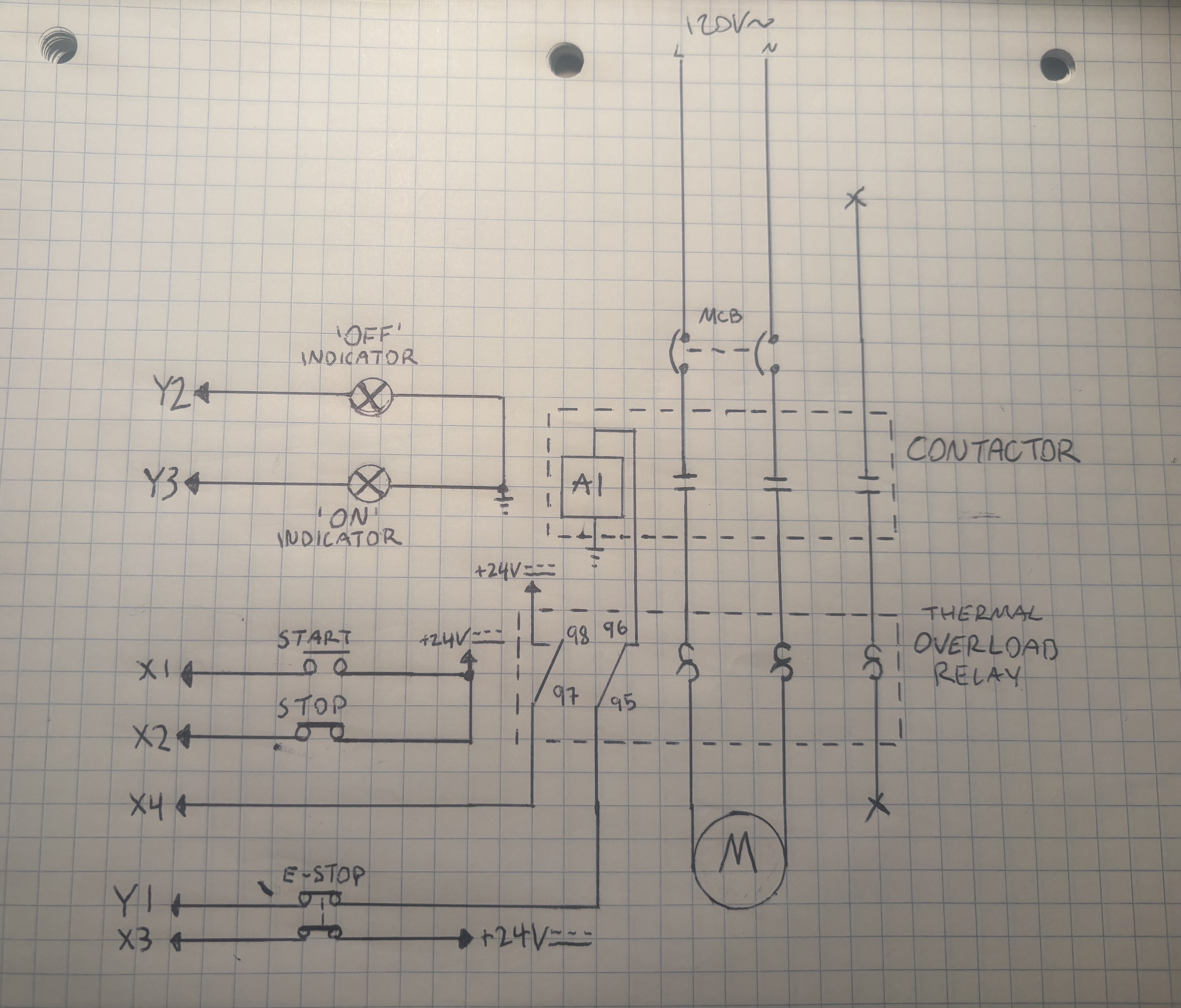
I began by sketching out different versions of the circuit and considered what kind of features I would want to implement beyond just simply starting and stopping the motor. An E-Stop and thermal overload immediately came to mind as two safety features I could easily integrate with both hardware and software.
The key detail in best utilizing both components was to place the E-Stop and overload NC contacts in series with the contactor coil for redundancy and reliable physical protection. I also decided adding indicators tied to the status of the motor would be a nice touch as well.
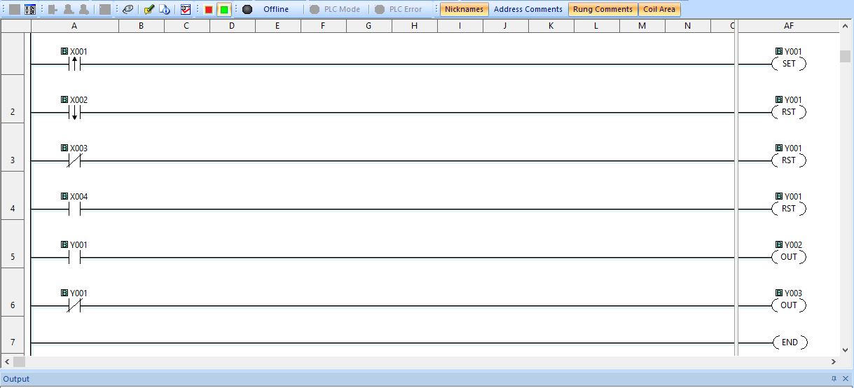
With my schematic drawn and components decided on, I began writing the program. I started out with just latching the output bit to the contactor coil via the momentary start button and unlatching it via the momentary stop button. I then integrated the secondary NC contacts of the E-Stop to send a signal to the PLC which would unlatch my contactor coil output if opened. The purpose of this is to prevent the motor from immediately restarting as soon as the E-Stop is reset and the physical connection to the coil is restored.
I followed a similar structure with the NO contact of the thermal overload relay. If these contacts close, there is a serious motor fault and it is critical that the contactor coil be de-energized. Lastly, I used the contactor coil output as XIC/XIO bits to turn on my green/red indicator lights on respectively based on whether or not the motor is running.
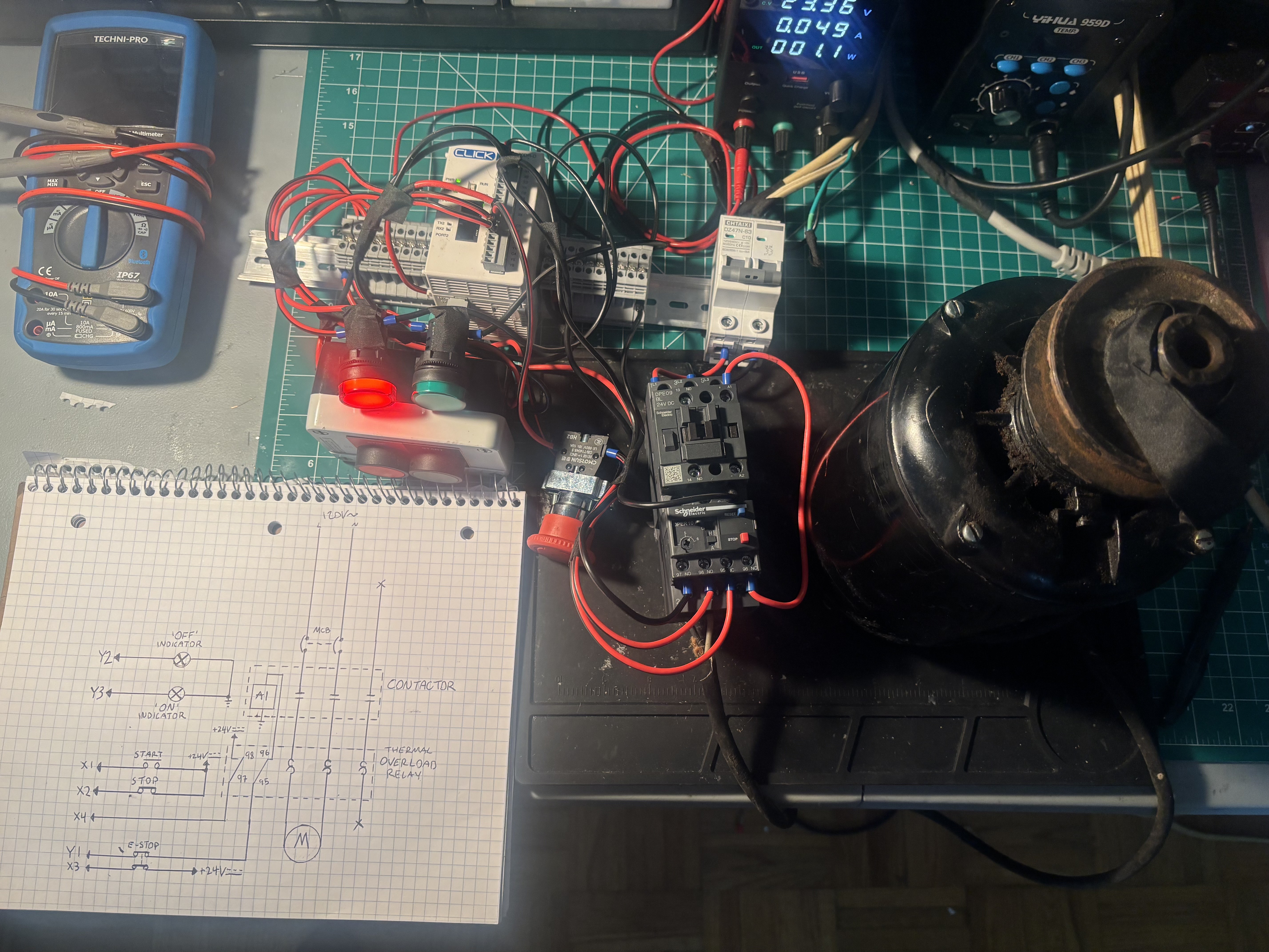
Here is the circuit in action. The program works exactly as intended to control the motor and ensure safe operation. Since this overload's NO contacts will only close if there is enough current flowing to bend the bimetallic strip inside it, I simulated this condition by manually jumping the PLC side to +24VDC. I am currently working on integrating analog inputs and displaying them on a virtual HMI via MODBUS for a mock tank level monitor and automatic pump circuit.