This 1.5 amp NAPA 12V battery maintainer was taken off a piece of equipment as it was no longer powering up or charging whatsoever.
I used my hot air soldering gun and a scalpel to carefully separate the case and gain access to the board. With the board exposed, I began a visual inspection to hopefully identify any obvious signs of failure before taking my measurements.
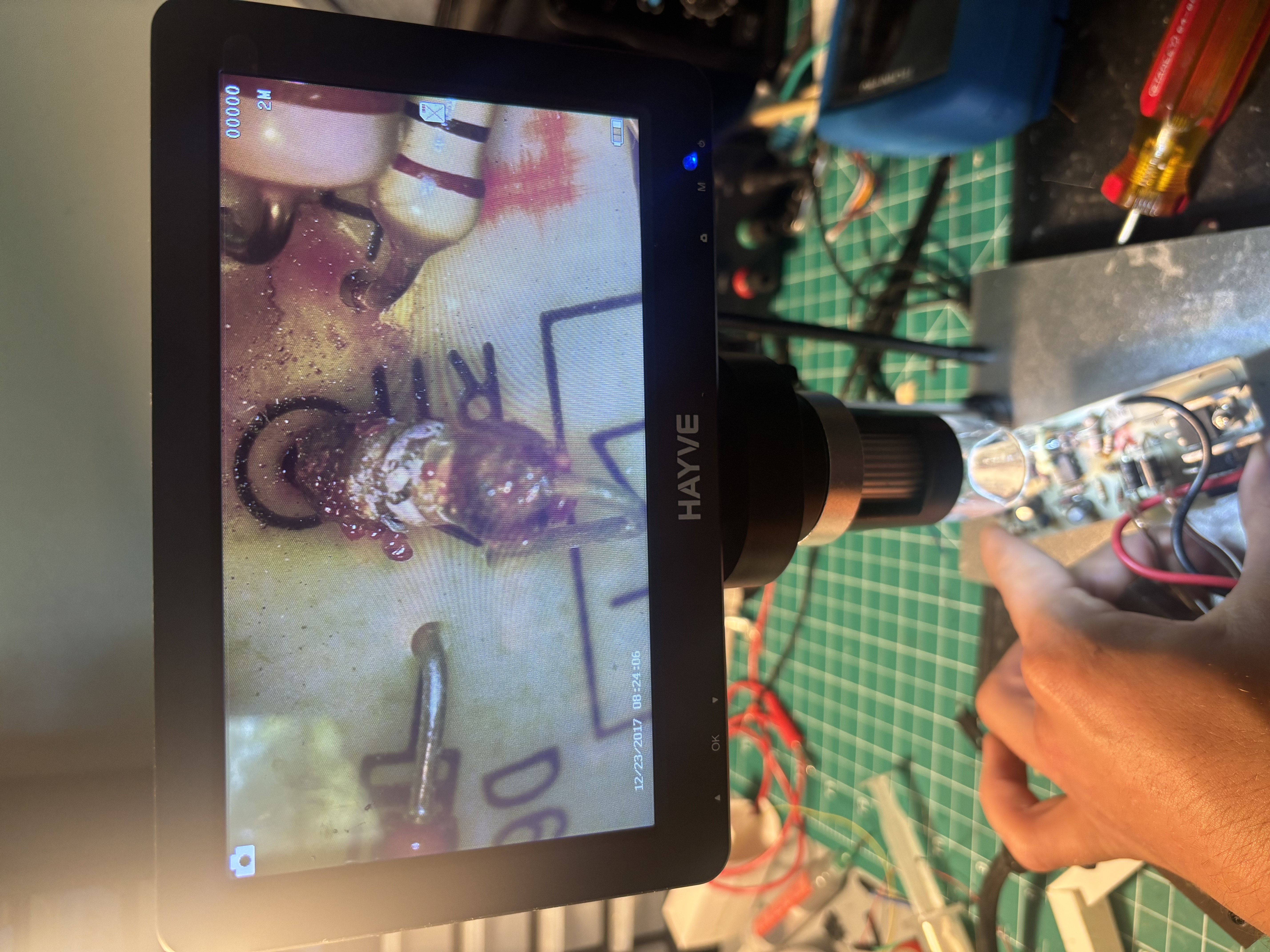
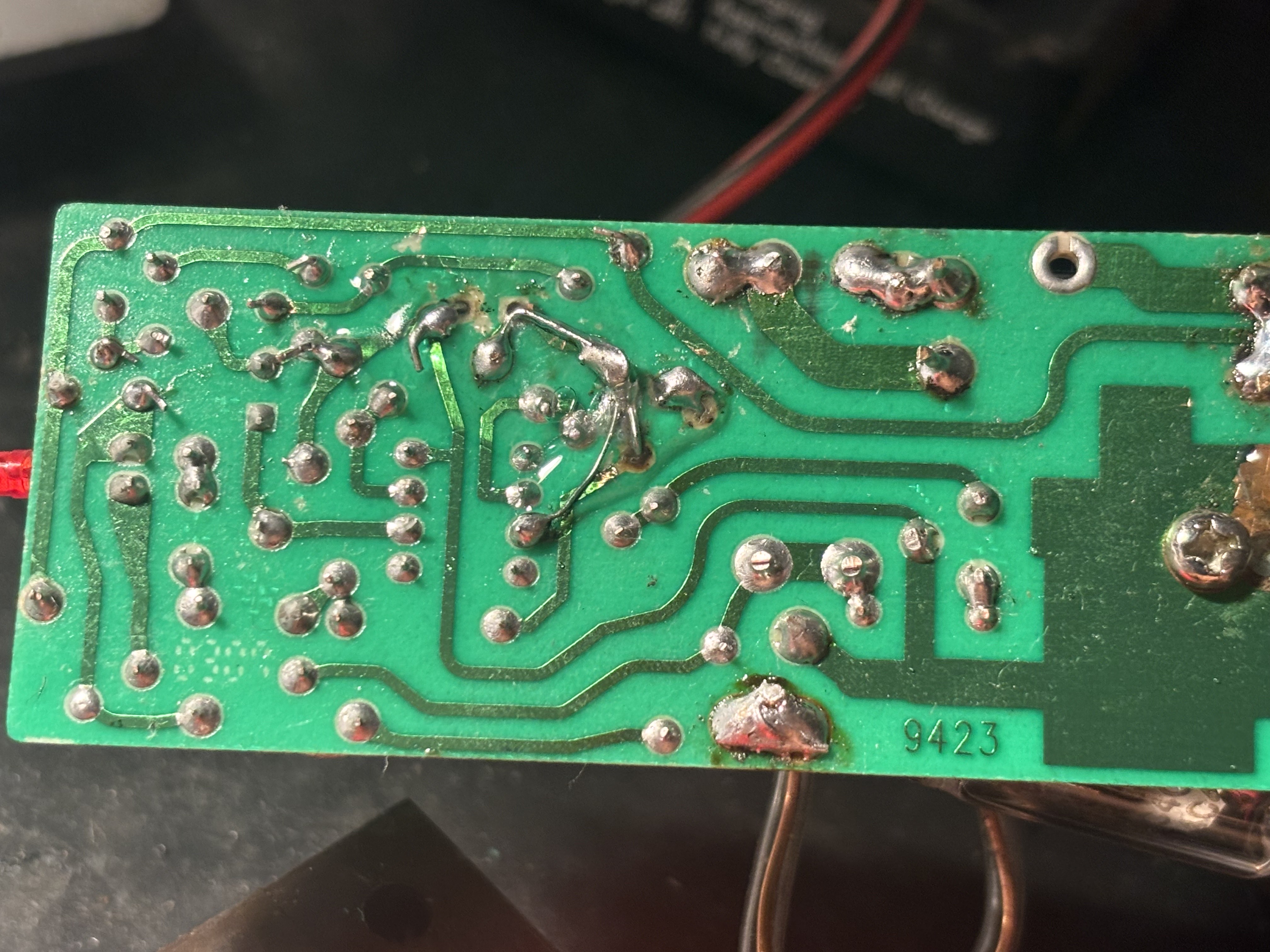
Visual inspection revealed visible corrosion on the positive-half rectifier diodes and a catastrophically failed resistor. There was no immediate evidence of a short circuit or excessive current passing through any other components fed off the same B+ rail. I began to suspect a cracked solder joint or lifted pad created enough heat to slowly bake the resistor into failure. My next step was to check the joint under a microscope and evaluate nearby components that may have also suffered thermal stress.
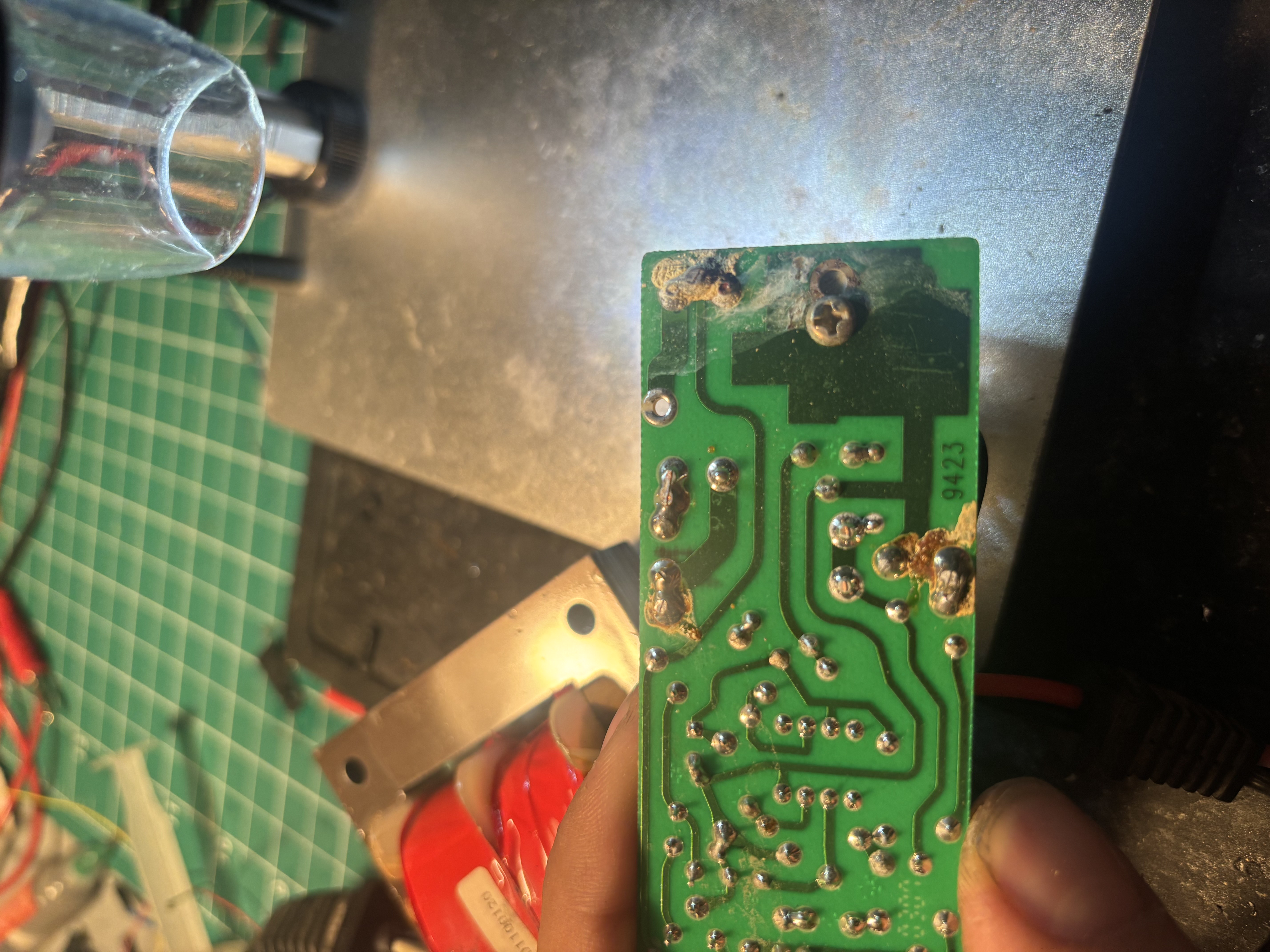
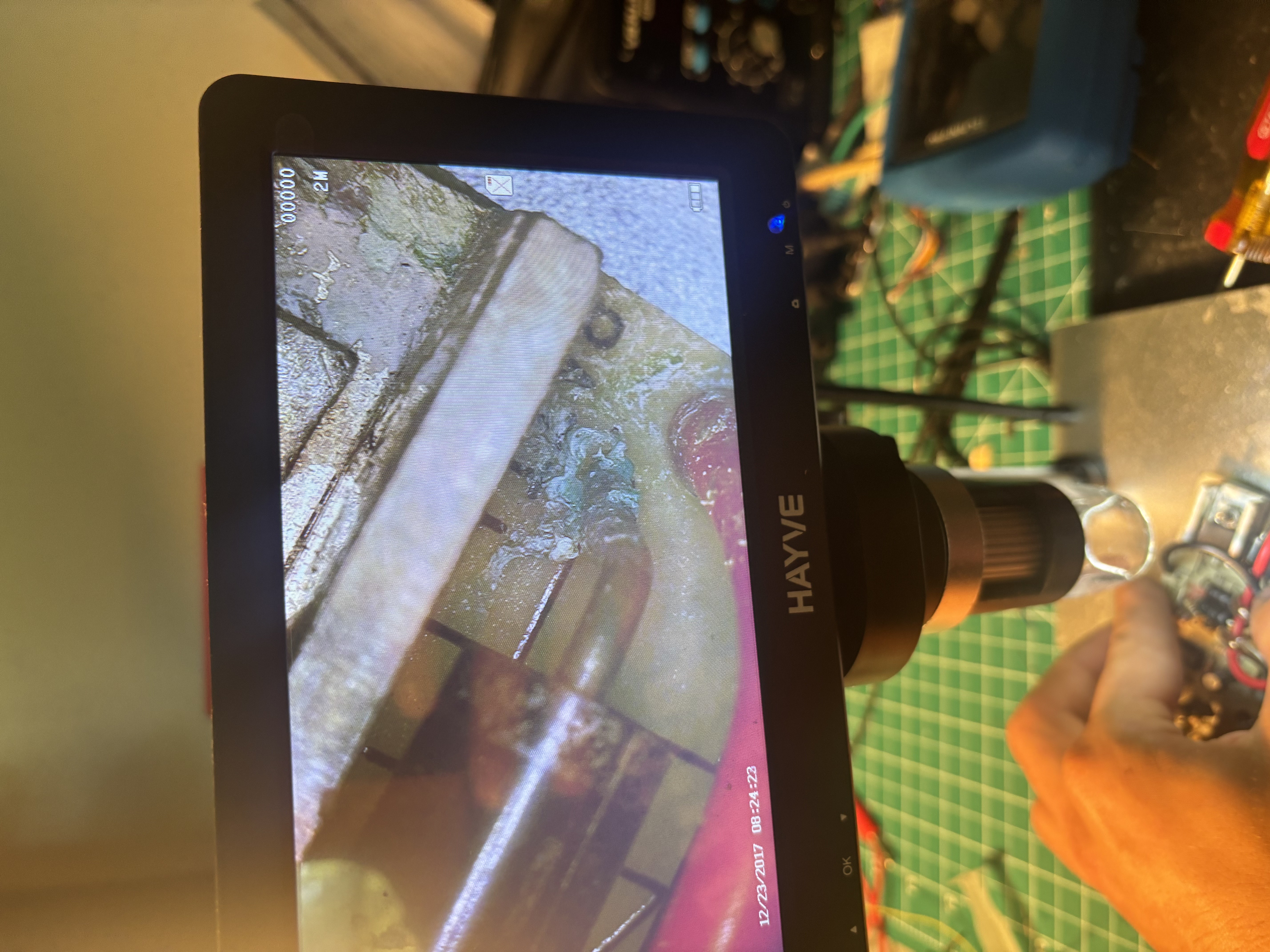
I discovered the pad for the failed resistor had almost completely lifted off the board. To properly determine its replacement value and verify operation of the nearby components, I needed to create a schematic. I used a multimeter to carefully measure each component and trace its path to get a full picture of the circuit.
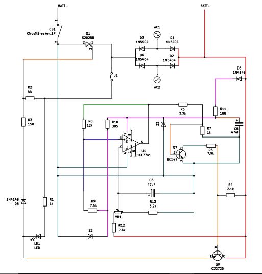
With a complete circuit diagram, I could now begin to determine the correct replacement value for the resistor. R11 is the series resistor responsible for supplying the op-amp's Vcc, Z3 bias current, and our non-inverting input. I could not get a model number off Z3, so I had to do some inference and math to find the right value. It was also found that the series diode (D6) failed shorted (likely due to thermal runaway) and the inverting input decoupling capacitor (C5) measured below 40uF putting it out of the +/- 10% spec.
The equation R1=VS−VZ/IZT+IL is used to determine a Zener diode's series resistor value. I consulted datasheets for the circuits components and some generic 12V Zeners to get the most accurate estimate of each value. R1=16-12/0.02+0.02, R1=100 ohms. With this identified, I created a parts list and began installing the new components.
A significant section of the trace leading to the op-amp supply was found to be lifted, so I used a piece of jumper wire to recreate the path. I sealed all my new connections with UV resin to protect and isolate them. I cleaned all the corrosion off and reflowed any questionable solder joints as needed.
I tested the unit with my power supply's constant current output mode. I verified that the maintainer would output at the correct threshold (just below 12VDC) which could be fine tuned further by adjusting the VR potentiometer on the inverting input.